
Some time ago I have bought a “noname” development board just for $1. There are a USB connector and two Zener diodes, two leds and a 8-pin header and a DIP-8 socket for ATTiny25/45/85 microcontroller. It can be powered from a USB port and can communicate via USB interface. This is a clone of the DigiSpark development board.
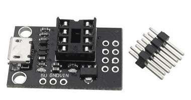
I have decided to insert my new ATtiny45 MCU into the DIP-socket. This MCU came from factory without any firmware. So, when I’ve connected the board to my PC with micro-USB cable, Windows said: “Unknown Device”.
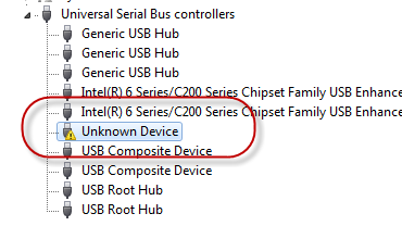
It took some time to solve this problem. Finally, Windows recognized the board and this guide will help you make this board working properly.
Step1: Programming ATtiny with Ardiono UNO
The ATtiny25/45/85 is a RISC 8-bit MCU with 2/4/8KByte program memory flash and 128/256/512 bytes of SRAM. There are 6 I/O lines, GND and VCC lines. ATtiny communication capabilities are based on USI (Universal Serial Interface). There is no direct hardware support for interfaces such as USB, SPI, I2C or UART. These interfaces are implemented in software. ATtiny can operate as a low speed USB device(1.5 Mb/s). Poor and limited communication features of the ATtiny are balanced with its small size, price and it is very easy to use. I think it is the best choice for running simple programs.
To make ATtiny work, you will need:
- Arduino UNO or AVR ISP (in-system programmer)
- ATtiny45 or ATtiny85
- 10uF 16-60V electrolytic capacitor
- a solderless breadboard and 6 wires
- led (optional)
Adding ATtiny support in Arduino IDE
1) Download and install the latest Arduino IDE.
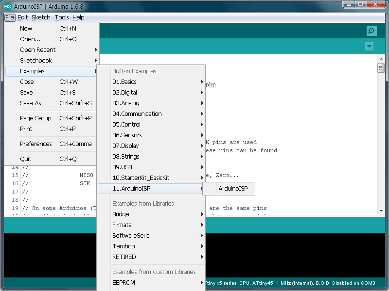
2) Turn your Arduino UNO into an ISP. Find and open sketch in the “File->Examples->ArduinoISP” and upload it into your Arduino board.
3) Disconnect you Arduino board from USB.
4) In the Arduino IDE go to the “File->Preferences” and configure your “Additional Boards Manager URLs”.
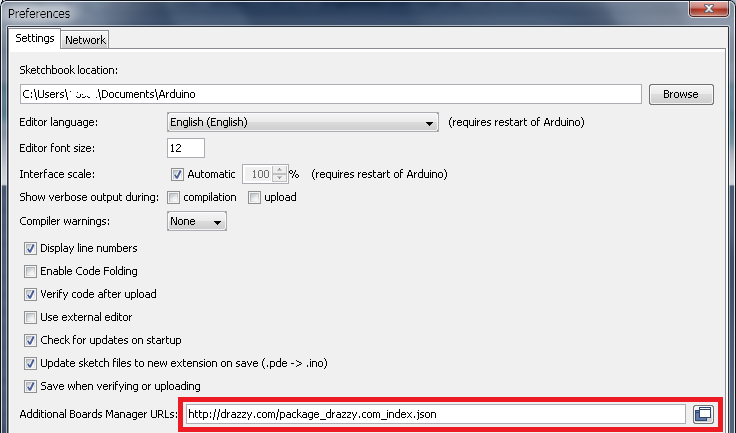
I prefer ATtinyCore library from Spence Konde. It supports many microcontrollers, clock frequencies and it works great for me.
ATtinyCore http://drazzy.com/package_drazzy.com_index.json
Digispark http://digistump.com/package_digistump_index.json
You can add both of these libraries, separate these URLs by comma.
Digispark core requires 1.6.5+ IDE and a ATtiny85 MCU.
5) Go to the “Tools->Board->Boards Manager” and Install these packages.
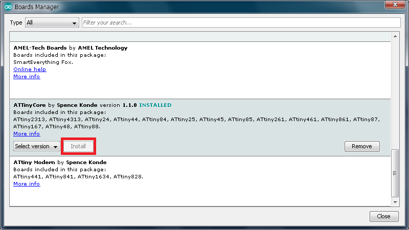
6) In the “Tools” menu you can select your ATtiny MCU, its clock frequency and other parameters.
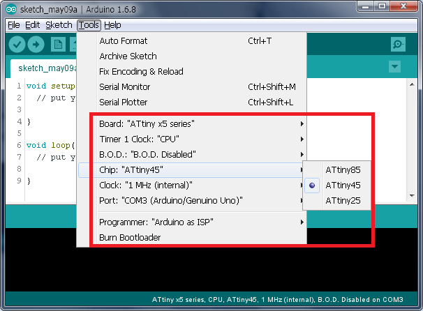
Warning: Do not select “External Clock”, because your MCU will not work any more without external oscillator!
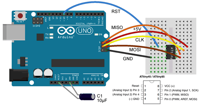
7) Wire your Arduino board to the target as shown in the diagram below. Connect MISO, MOSI, SCK, RESET, VCC, and GND of the programmer to the corresponding pins on the ATtiny. Add a 10 uF capacitor between reset and ground pins (long pin “+” to RST, short pin “-” to GND).
Programming the ATtiny
Now your Arduino UNO is configured as a serial programmer (ISP) that can upload firmware into other Atmel chips. Select it in the IDE menu “Tools->Programmer: Arduino as ISP”.
Lets write a simple blinking firmware and test it with the development board. I should mention that there are two red leds on the board. They are – the power led and the user led on PB1 pin.
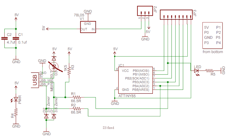
Thanks to “milami” who has found the error with D3 Schottky diode.
You can compile and upload any blinking sketch into the ATtiny. When you finished uploading sketch extract your MCU from the breadboard and insert it into the DIP socket in the development board. Connect the USB cable and you will see the blinking led.
// Blinking firmware for ATTiny45 (25,85) MCU
byte ledPin = 1;

void setup()
{
  pinMode(ledPin, OUTPUT);
}

void loop()
{
  digitalWrite(ledPin, HIGH);
  delay(500);
  digitalWrite(ledPin, LOW);
  delay(500);
}
I believe this is the best way of a ATtiny usage, because it takes minimum MCU resources and doesn’t depend on any bootloader and it is easy as Arduino.
Step2: Burning a bootloader into ATtiny MCU
Now its time to find out why this board is called the development board. It is called so because it can program itself. It is a great idea to connect the board to a USB port and upload almost any sketch into it. Guys in Digistamp thought the same way. Their boards are based on ATtiny85 MCU with the micronucleus bootloader.
A BootLoader is a code which executes when a microcontroller is powered ON or after reset. It receives new program information externally via some communication interfaces (USB, SPI, UART) and writes that information to the program memory (flash) of the processor. The device provides a Self-Programming mechanism for downloading and uploading program code by the MCU itself.
Micronucleus is a bootloader designed for ATtiny series MCU with a minimal USB interface. It allows ATtiny to act like a USB device. It always resides in flash memory, utilizes interrupts and receives user code via USB and stores it in flash. It runs the user code loaded into it after a 5 second delay if it does not receive a request to upload new code within that 5 seconds.
ATtiny MCU has no hardware support for USB interface. To operate properly the MCU must run at a high clock frequency 16MHz+. The clock frequency is configured by setting the fuses bits.
In the previous step the ATtiny device was still “Unknown” to the Windows. To make it a valid USB device we need a firmware with some USB support. Usually the firmware is distributed as a HEX-file. There is a command line utility “AVRDUDE” in the Arduino IDE, and it is used to upload hex-files into the MCU. This utility works behind the scene in the Arduino IDE. I prefer AVRDUDESS – a GUI for AVRDUDE, a tool for programming Atmel microcontrollers.
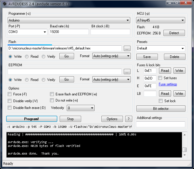
This application automatically detects paths to the “avrdude.exe” and the “avrdude.conf” files. It supports many programmers and microcontrollers (Atmel). Select appropriate options and press the “Program!” button.
When you have finished burning micronucleus and set fuse bits (frequency 16Mhz and Self-Programming Enable) you can insert your ATtiny MCU into the development board, connect it to any USB port and finally install LibUsb-win32 drivers. The board is ready!
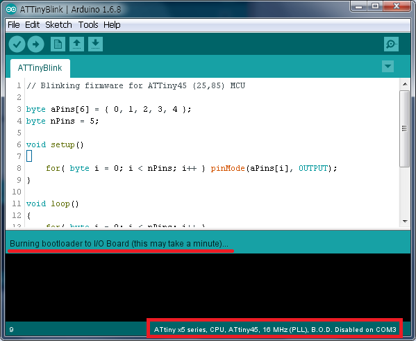
In the Arduino IDE you can write a sketch for the ATtiny85 MCU and upload it via USB. You can open our blinking sketch or “File->Examples->Digispark_Examples->Start” and build it. You will see the prompt to connect the board. When the development board is connected the IDE will upload your sketch into it.
I could successfully program my ATtiny45 MCU, but unfortunately it does not execute my blinking code. I think the board and the Digispark software requires ATtiny85 MCU only. Or may be I should convert RESET pin to I/O pin, but I don’t want to brick my ATtiny right now.
Sketch uses 794 bytes (13%) of program storage space. Maximum is 6,012 bytes.
Global variables use 17 bytes of dynamic memory.
Running Digispark Uploader...
Plug in device now... (will timeout in 60 seconds)
> Please plug in the device ...
> Press CTRL+C to terminate the program.
> Device is found!
...
running: 100 complete
>> Micronucleus done. Thank you!
I should mention one interesting project from Japan. AVR-CDC converts USB and RS-232C signals using the ATtiny MCU. AVR-CDC enables PC to communicate with the USB device through virtual COM port. This experimental software is based on LibUsb-win32 libraries, but its Windows drivers are not digitally signed, however, the firmware is great.
Step 3: Ode to fuses
Another great feature of the AVRDUDESS application is to read and write MCU fuses (configuration registers). An ATtiny fuse has nothing similar to fuses you know from electrical devices. ATtiny25/45/85 has three fuse bytes – Low, High, Extended. These registers control the behavior of the MCU when it starts. Most of these fuses have a strong influence on the way to program an ATtiny, its operating frequencies and conditions.
There are five important configuration fuses:
- clock source and frequency;
- SPI programming enable;
- reset pin disable;
- self-programming feature;
- brown-out detection.
To make our development board a full compatible to Digispark, we need a 6-pin I/O version of the MCU. Think twice and upload reliable bootloader first, before disabling the RESET pin!
Converting RESET pin to I/O pin (PB5) disables further programming of the MCU over SPI. This is because ISP requires the RESET pin. You will need a HVSP (high-voltage serial programmer, 12V) programmer to clear the fuses. If you burn the fuse before the program is correctly loaded, you cannot program it with ISP.
There is a great project that can unlock and recover ATtiny fuses with Arduino UNO as a high voltage programmer. Of course, to rescue your bricked ATtiny you will need a transistor, several resistors and a 12V power supply.
It is possible to burn some fuses in the Arduino IDE. It can be done with the “Burn Bootloader” command from the Tools menu. This doesn’t actually burn a bootloader into the board! This configures the fuse bits of the microcontroller so it runs at required frequency (1, 8 or 16 MHz). Note that the fuse bits keep their value until you explicitly change them, so you only need to do this step once for each microcontroller.
It is possible to use command-line utility for programming (suppose the PATH variable is set correctly):
avrdude -c arduino -p t45 -P COM3 -b 19200 -U lfuse:w:0xE1:m -U hfuse:w:0xDD:m -U efuse:w:0xFE:m
I use the following values for fuses in my ATtiny45 – Internal 16Mhz clock, self-programming mode enabled, normal RESET pin:
| Fuse | Value |
|---|---|
| Low | 0xE1 |
| High | 0xDD |
| Extended | 0xFE |
Conclusion
The 8 pin ATTiny45 (85) is a very small but powerful controller. It is NOT designed to work efficiently with the USB. It does not have a dedicated USB hardware. As a result, a very poor software implementation is used. It uses most of the resources and does not support minimum features of the USB interface. Bootloaders are “resident” programs that highly utilize interrupt handlers to process USB request from the host PC. However, the ATtiny does not have enough resources to reply to the host in time, so the device is not stable and frequently gets disconnected. It is compatible almost with nothing and needs special software and drivers to communicate.
The communication is very slow and transfers several bytes at time with peak speed of 9600 bps. But even this is not the biggest issue. The biggest issue is that there is not enough flash and SRAM memory to fit most applications. The USB library takes half of resources. This is not enough even for another library. Unfortunately, forget about this devices unless all you need is just to blink the LED or to transmit dozen of bytes.
I think the board has some potential. It can be used as a programmer (TinyISP) or a slow USB to UART/SPI/I2C converter. Also it can transmit data from various sensors (temperature, pressure, e.t.c.) into the PC.
Pingback: Attiny85 development board – Aztectrev Projects