
Hello, friends.
Take a look at this great multi-functional shield for the Arduino UNO R3. This shield can be inserted into the Arduino header and it requires no additional power supply.
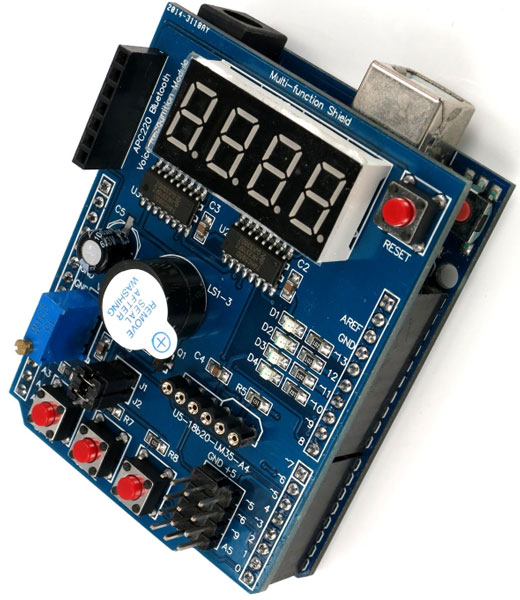
Some shields have too long pins under the 7-segment led tube and may contact USB connector. This will produce garbage on the 7-segment tube. You should cut long pins under the display or isolate the USB connector on your Arduino.
The shield has a wide range of features which makes it perfect for beginners who want to study. It can be useful for advanced users because it has built-in general purpose components:
| Unit | PIN # |
|---|---|
| 4 red LEDs | 10, 11, 12, 13 |
| 3 buttons + reset button | A1, A2, A3 |
| Potentiometer (10 kOhm) | A0 |
| 4-digit 7-sement LED tube driven by 74HC595 | Latch 4, Clock 7, Data 8 |
| Buzzer (loud speaker/beeper) | 3 (digital On/Off) |
| Socket for infrared receiver (remote control) | 2 |
| Socket for temperature sensor LM35 or DS18B20 | A4 |
| Header for APC220 shield | GND, +5v, 0, 1 (rx/tx) |
| Free pins (pwm) | 5, 6, 9, A5 |
Also you will find a connector with 4 free pins, 4 pins GND, and 4 pins with +5V.
I have dig the Internet and found the datasheet and some sample C-programs. Documentation is scarce, but the shield is simple and everything is visible and obvious. You can find links to these docs at the end of this post.
The first program in the microprocessor world is a blink sample firmware.
Before you write your own sketch for this multi-function shield remember that most of its units are connected to +5 volts. Look at this part of datasheet:
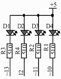
As you can see anodes of LEDs (D1, D2, D3, D4) are connected to +5, and cathodes are connected to the Arduino PINs through resistors 510 Ohm (R1,R2, R3, R4). The LED will light when the pin is in a LOW state. You might know that the 13 pin in the Arduino is connected to the LED. The same pin is used in this multi-function board to light LED D1. The sample sketch will show the difference of the conection schema. When the Arduino LED is ON, the multi-function shield LED is OFF (and vice versa).
void setup()
{
    pinMode(13, OUTPUT);
}

void loop()
{
    // led On
    digitalWrite(13, LOW);
    delay(1000);
    // led Off
    digitalWrite(13, HIGH);
    delay(1000);
}
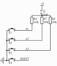
The multi-function shield has 3 user buttons. These switches (keys) have pull-up resistors 10 k. NOTE: Pressing any key generates LOW logic signal. Such design could be complex for beginners.
The next step is to write a sketch that utilizes user button and produces sound through the on-board buzzer.
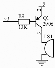
The buzzer on this multi-function shield is loud enough because it is connected to the transistor Q1. This p-n-p transistor makes it beep when the signal is LOW on #3 pin. In the datasheet you can see the connection circuit.
You might know about the “tone()” function in the Arduino library that could be used to generate sound. Unfortunately this function cannot be used with my multi-function shield.
In the Arduino world the “tone()” function assumes that the buzzer is pulled down to the GND and it is silent when the corresponding pin ‘3’ is in a LOW state. However, the buzzer in my multi-function shield is silent when the pin is in a HIGH state.
As I have mentioned above, the buzzer is driven by the transistor Q1. AFAIK, this transistor amplifies the signal and the active buzzer generates fixed frequency sound wave. Thus we cannot change the frequency of the sound. When the LOW signal arrives on the base terminal of the p-n-p transistor the emitter (+5) and collector currents rise. Somehow, this transistor works like a switch. Active buzzer contains an internal oscillator and it beeps when a DC voltage is applied. Even if we try the “tone()” function which switches the pin state from LOW to HIGH the frequency of the beeper does not change.
#define ON             LOW
#define OFF            HIGH

void setup()
{
    // configure pins
    pinMode(A1, INPUT);
    pinMode(3,  OUTPUT);
    // default: sound Off
    digitalWrite(3, OFF);
}

void loop()
{
    // whait KEY1 press
    if( digitalRead(A1)==ON )
    {
        // sound ON
        digitalWrite(3, ON);
    }
    else
    {
        // sound OFF
        digitalWrite(3, OFF);
    }
}
Although pin #3 supports PWM it is still a digital pin without DAC, and it can generate only digital signals LOW and HIGH.
LM35 Temperature sensor
Remove jumper J1.
5 responses to Multi-function shield for Arduino