
I have been designing PCBs a lot during past years. Besides I’ve got a mathematical education and I have some experience to share. Here are some of the best practices I have gathered from years of working on and using it myself.
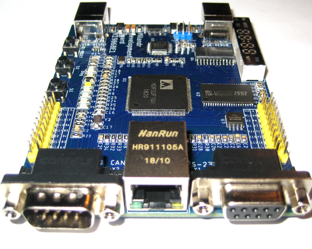
1. First of all, place the IC with a largest number of pins in the center of your PCB. Usually it is a CPU, MCU or a memory module. Any integrated component (IC) placed in the center of PCB has shortest routes to any other component. Make routes on your PCB as short as possible.
2. Connectors should be placed close to the edge of your PCB. This will let users to connect your board to other devices.
3. Place interface transceivers ICs between cable connector and CPU (MCU). The rest components should be placed at free space. Keep in mind that every IC needs some free space for its signal lines. More lines – more space is required!
4. Start the PCB routing with buses. The most complex task is to connect a CPU (MCU) and memory IC. Address and data lines should be of equal length without crossing. Differential signal lines, such as crystal oscillator, are also very important. Keep them short and straight.
5. Power supply lines needs your attention. It is a good practice to use bottom layer as a GND plane for a 2-layers PCB. In a 4+ layers PCB internal layers are used as GND and VDD planes. When you need to connect a pin to GND plane – make a via. Think of supply lines as a water pipes. Try to make it straight and simple!
6. Capacitors should be placed close to IC for bypassing and decoupling purposes. Place capacitor for every power consuming IC! Read the routing recommendations in the IC datasheet.
7. You should place the lowest value capacitor closest to the device pin. When possible place capacitors on the bottom side of the PCB.
8. Place resistors, capacitors, diodes, transistors etc close to each other, but always keep in mind how to solder and access these components. Rotate and move components to minimize routes. Short routes require less PCB space and reduces EMI noise.
9. User auto-router from time to time. Analyze its results, draw easy routes immediately. Try to figure out complex routes and simplify your PCB to avoid locks. Avoid parallel signal lines in different layers. It will make parasitic capacitance and will make PCB routing difficult.
10. Use reference designs provided by manufacturers.
Feel free to share your experience and comment out these PCB routing rules.