
Hello.
In this post I will show how to connect and drive 4-Digit 7-Segment LED Display with Ardino UNO.
Recently I have posted a topic on how to drive a single 7-segment LED Display. I think it was simple, but it requires lots of wires. Usually we need to display numbers that consist of multiple digits. For this purpose it is possible to find 4-Digit 7-Segment LED Displays with Common Anode or Common Cathode in the market.
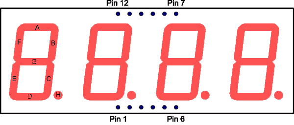
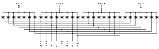
The module contains four 7-segment LED numeric displays. These digits can be turned on and off independently. Each of the four digits in the module uses its own common cathode (or common anode) connection point. It means that every segment (line) shares the same anode (or cathode) connection points. Segments are labeled: A, B, C, D, E, F, G, H (for dot). Every segment is connected to all four digits. This reduces the wiring required (4+8=12 vs 4×8=32).
There are 12 connection points = 4 PINs are used for digits + 8 PINs are used for segments (lines).
The most important difference between 1-digit and 4-digit displays is the way we turn ON and OFF segments. To light multiple digits we use ‘multiplexing’.
We display 4-digits at once by rapidly cycling through them in infinite loop.
1) Turn ON active digit by switching its PIN connected to common cathode (anode).
2) Determine the list of segments to turn ON and light these segments.
3) Wait for some time (2-5 ms).
4) Turn OFF the digit (cathode and all segments).
6) Select next digit in list [1…4].
Arduino UNO R3 Specification says that maximum current per PIN is 40 mA. So we need some limiting resistors. To light a LED we need approximately 15 mA. Resistor value can be calculated as:
R = V / I,
V = 5 volt
I = 10..20 mA
R = 220…470 Ohms
Some people aware of too much current in the circuit when all the segments are switched on. The current will be 7 * 20mA = 140 mA, or 7 * 10 mA = 70 mA (depends on resistor value). This current is safe for Arduino, but will damage STM32 MCU (transistors can solve this problem).
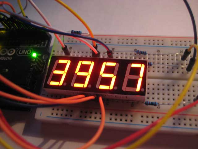
Now its time to connect my SMA420564 4-digit 7-segment LED display to Arduino UNO. Required components are available in The Arduino UNO Basic Learning Kit. We need 4 resistors, breadboard and 12 wires. Connect limiting 470 Ohm resistors to 12, 9, 8, 6 PIN of the 4-Digit LED Display. Wires should be connected according to this table:
| Name (LED pin) | Arduino pin |
|---|---|
| Digit 1 (PIN 12) | A0 |
| Digit 2 (PIN 9) | A1 |
| Digit 3 (PIN 8) | A2 |
| Digit 4 (PIN 6) | A3 |
| Segment A (PIN 11) | D3 |
| Segment B (PIN 7) | D4 |
| Segment C (PIN 4) | D5 |
| Segment D (PIN 2) | D6 |
| Segment E (PIN 1) | D7 |
| Segment F (PIN 10) | D8 |
| Segment G (PIN 6) | D9 |
Segment DP or dot (pin 3) is not used in this sketch.
Never use pins 0, 1 and 13. Specially digital pin 0 and pin 1 are used for serial communication (RX/TX ) like “Serial.begin(9600)”
Analog PINs A0-A3 can work in digital mode, so we use these pins to drive digits. These PINS will be used as common cathodes. The display is multiplexed, so we select the digit by setting its pin LOW (make it GND/cathode), and then we light segments by setting thier pins HIGH (anode).
Lets take a look at the code:
int segA = 3; // top
int segB = 4; // right-top
int segC = 5; // right-bottom
int segD = 6; // bottom
int segE = 7; // left-bottom
int segF = 8; // left-top
int segG = 9; // middle

int digit1 = 14; // common cathode for digit1 (i.e. A0)
int digit2 = 15; // common cathode for digit2 (i.e. A1)
int digit3 = 16; // common cathode for digit3 (i.e. A2)
int digit4 = 17; // common cathode for digit4 (i.e. A3)

// Number to display
static int number = 0;
static int ms = 0;

//==============================================================//
void setup()
{
    // All pins in digital mode
    pinMode(digit1, OUTPUT);
    pinMode(digit2, OUTPUT);
    pinMode(digit3, OUTPUT);
    pinMode(digit4, OUTPUT);

    pinMode(segA, OUTPUT);
    pinMode(segB, OUTPUT);
    pinMode(segC, OUTPUT);
    pinMode(segD, OUTPUT);
    pinMode(segE, OUTPUT);
    pinMode(segF, OUTPUT);
    pinMode(segG, OUTPUT);
}

//==============================================================//
void loop() {
    // put your main code here, to run repeatedly:

    if( millis() / 1000 > ms )
    {
        ms = millis() / 1000;
        if( ++number > 9999 ) number = 0;
    }

    // activate common cathode for digit1
    digitalWrite(digit1, LOW);
        // light on segments for 'thousands'
        drawDigitFast( (number/1000) % 10 );
        // wait 2 ms
        delay(2);
        // turn off all segments
        drawDigitFast( -1 );
    // turn off cathode for digit1
    digitalWrite(digit1, HIGH);

    digitalWrite(digit2, LOW);
        drawDigitFast( (number/100) % 10 );
        delay(2);
        drawDigitFast( -1 );
    digitalWrite(digit2, HIGH);

    digitalWrite(digit3, LOW);
        drawDigitFast( (number/10) % 10 );
        delay(2);
        drawDigitFast( -1 );
    digitalWrite(digit3, HIGH);

    digitalWrite(digit4, LOW);
        drawDigitFast( number % 10 );
        delay(2);
        drawDigitFast( -1 );
    digitalWrite(digit4, HIGH);
}

//-----------------------------------------------------//
void drawDigitFast(int n)
{
    const byte aPins[8] = {
        segA, segB, segC, segD, segE, segF, segG
    };
    const byte aSegments[11][8] = {
        //  A     B     C     D     E     F     G
        { HIGH, HIGH, HIGH, HIGH, HIGH, HIGH,  LOW }, // 0
        {  LOW, HIGH, HIGH,  LOW,  LOW,  LOW,  LOW }, // 1
        { HIGH, HIGH,  LOW, HIGH, HIGH,  LOW, HIGH }, // 2
        { HIGH, HIGH, HIGH, HIGH,  LOW,  LOW, HIGH }, // 3
        {  LOW, HIGH, HIGH,  LOW,  LOW, HIGH, HIGH }, // 4
        { HIGH,  LOW, HIGH, HIGH,  LOW, HIGH, HIGH }, // 5
        { HIGH,  LOW, HIGH, HIGH, HIGH, HIGH, HIGH }, // 6
        { HIGH, HIGH, HIGH,  LOW,  LOW,  LOW, LOW  }, // 7
        { HIGH, HIGH, HIGH, HIGH, HIGH, HIGH, HIGH }, // 8
        { HIGH, HIGH, HIGH, HIGH,  LOW, HIGH, HIGH }, // 9
        {  LOW,  LOW,  LOW,  LOW,  LOW,  LOW,  LOW }  // all off
    };

    if( n < 0 || n > 10 )
    {
        n = 10;
    }

    for( int i = 0; i < 7; i++ )
    {
        digitalWrite( aPins[i], aSegments[n][i] );
    }
}
What we’ve got:
In this video you can see flickering and also some segments are still turned on. I made this video with bug in the sketch. It is important to turn off all segments after the delay, i.e. call drawDigitFast(-1);
P.S. I like these articles:
http://learn.parallax.com/4-digit-7-segment-led-display-arduino-demo (uses transistors)
http://www.instructables.com/id/Arduino-4-digit-7-segment-display/ (flickering, but simple code)
http://www.hobbytronics.co.uk/arduino-4digit-7segment (nice brightness control)
http://www.hacktronics.com/Tutorials/arduino-and-7-segment-led.html (cool blue led)
The sketch source code is available in this GitHub repository.