
I. Introduction to the CC1310.
If you are reading this article you should know that the CC1310 is a Sub-1 GHz wireless microcontroller based on a Cortex-M3 processor running at 48Mhz. It is equipped with 32 (or 64/128) programmable flash and 20KB SRAM. The CC1310 in the QFN48 package supports 30 GPIO, 12-bit ADC, UART, 2xSPI, I2C, I2S, AES-128 and temperature sensor. Friendly speaking, these features of the CC1310 microcontroller does not impress me.
The most interesting and useful subsystem in the CC1310 device is an integrated RF transceiver. This dedicated radio controller (Cortex-M0) handles low-level RF protocol commands. At the release time the Texas Instruments has published RF parameters of the CC1310 device and declared speed up to 4000 kbps, output power 15dBm and sensitivity -124dBm. They promised 625bps in a long range mode (up to 20km).
Now in the datasheet (page 16) you will find that the maximum data rate is 50kbps. The web site does not mention about RF data rates at all.
The problem is that the product specifications declared once on the manufacturer site does not match the real characteristics of the CC1310 device. This new chip has lots of features that sometimes work and sometimes do not.
II. A brief look at the CC1310 errata
In the October 26, 2016 TI has published second (rev.A) errata for the CC1310 device.
This is the most frustrating document I have ever read on the manufacturers’ web site. I was very much upset reading this:
“Data Rates Not Yet Supported. The supported data rate is up to 100 kbps. Support for higher data rates will be added to the CC1310 at a later time. Functional testing at data rates over 100 kbps has been performed, but full characterization is not yet completed.”
continue
“Frequency Bands Not Yet Supported. The supported frequency bands at product release are 863 MHz to 876 MHz and 902 MHz to 928 MHz CC1310 die rev B and later adds support for frequency bands in the 431-MHz to 527-MHz range. Support for the 315-and 779-MHz frequency bands may be added to the CC1310 at a later time.”
finally
“Modulation Formats Not Yet Supported. 4-FSK is not yet supported.”
This fatal series of bugs make me really sad. In my dreams I have a plan to build my own flight controller based on this CC1310 RF-device. I would like to transmit up to 4000kbps over 1 kilometer, but it is “not yet competed”. I have read this errata several times and finally I’ve got a hope. The phrase “functional testing has been performed” gave me this hope. The errata does not say that the higher data rates are not supported. So it is possible to achieve higher data rates! First of all we need to understand the RF fundamentals.
III. How to speed up your CC1310 device
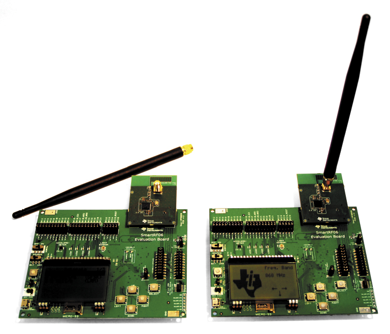
There is a wonderful utility from TI named SmartRF Studio. It can be used to program, configure RF registers, transmit/receive data and test many features of the CC-devices.
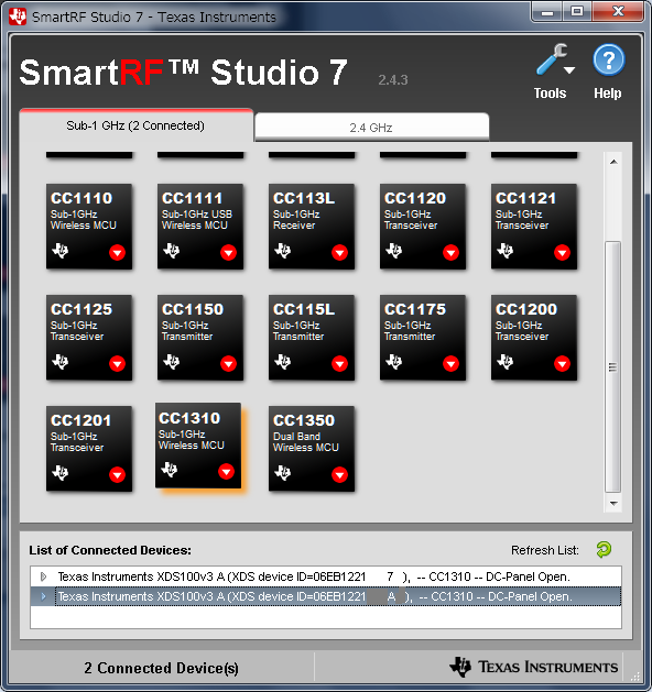
The main window contains a set of icons labeled with titles of the supported CC-devices. In the bottom of the main window you will find a list box of connected devices. Every CC1310 device has its own unique hardware id. We need at least two devices – first as a transmitter and second as a receiver.
When you double click on a list item the Device Control Panel will open. There are several input boxes and drop-down lists for configuring TX/RX parameters. Four tabs in the bottom of the control panel are used to transmit or receive radio packets. The Device Control Panel for the CC1310 chip differs from the panel we used to configure CC2510/CC2511 chips. The main difference is the window with RF configuration registers.
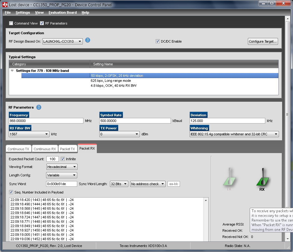
There are only three default presets for low speed RF-modes – 50kbps, 625bps, 4.8kbps. I have found values to configure the CC1310 for higher data rates. The Device Control Panel limits the symbol rate to 500kbps, but it is possible to use 500+ kbps data rates in your own firmware. First of all we will try 500kbps data rate mode. I cannot get reliable communication at 1 Mbps, yet.
We need to configure the cc1310 transmitter according to required frequency, modulation, channel width, etc. I would recommend to read and understand the basics of the frequency modulation and the frequency shift keying.
“The maximum frequency deviation is δ = 0.25 fm, where fm is the maximum modulating frequency. As a result, the modulation index m is 0.5. This is the smallest FSK modulation index that can be chosen such that the waveforms for 0 and 1 are orthogonal.”
For example, in the 50kbps mode TI uses 25 kHz deviation. For the 500kbps data rate the deviation should be 250 kHz. I even tried 125 kHz deviation and it seems to work fine. I think the bigger deviation requires wider filter for the receiver and will finally decrease the range.
The most important parameter for the receiver is the “RX filter BW” (filter bandwidth). Guys from TI use 98 kHz for the 50kbps data rate, so we should use at least 1243 kHz for the 500kbps. I have chosen 1567 kHz for the RX filter BW value. I have tested several combinations and put them in this table.
| Speed | Deviation | preScale | RateWord | BandWidth |
|---|---|---|---|---|
| 50 kbps | 25 kHz 0x64 | 0x0F | 0x8000 | 0x24 98kHz |
| 250 kbps | 125 kHz 0x1F4 | 0x06 | 0x10000 | 0x2E 942kHz |
| 500 kbps | 250 kHz 0x3E8 | 0x06 | 0x20000 | 0x30 1567kHz |
| 500 kHz 0x7D0 | 0x04 | 0x20000 | 0x32 2487kHz | |
| 1 MHz 0xFA0 | 0x06 | 0x40000 | 0x34 3767kHz |
Finally we can select some data whitening technique to improve quality of the transmission. It is possible to add CRC (16/32 bit) codes to every packet or another error correction codes.
IV. Making changes to the firmware
The last step is to modify your RF initialization functions in your source code. Texas Instruments recommends to use their example projects as a reference design for our own firmware. In the Code Composer Studio (CCS) you should open rfPacketTx (or RX) project and find “smartrf_settings” subfolder. There is “smartrf_settings.c” file with the structure RF_cmdPropRadioDivSetup.

We should modify the structure members: deviation, preScale, rateWord, rxBw, whitenMode (optional). Values are listed in the table above. By the way, you can find this values in the SmartRF Studio under menu item: File -> Code Export.

P.S. This article is based on the errata published in December 2016.
P.P.S. I cannot get reliable 1+ Mbps data rates, so any help is appreciated.