
Hello.
SmartRF Packet Sniffer is a great and useful tool for testing and debugging firmware. It supports many radio protocols used in Texas Instruments devices, such as ZigBee, SimpliciTI, BLE, RF4CE and generic (raw packets).
1. Tools required for RF Packet Sniffer
The SmartRF Packet Sniffer is a PC software for listening and displaying radio packets. It can be used with Chipcon/TI CC-series RF-devices (ChipCon was bought by TI in 2006). In this post we will use SmartRF04EB (cc2510) development board for transmitting radio packets at 2.4GHz. The CC2511 USB-dongle will be used as a receiver and a hardware platform for SmartRF Packet Sniffer.
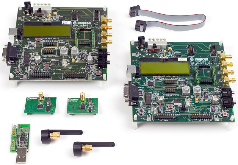
The SmartRF04EB board should be programmed with any transmitter. For example, “per-test” sample firmware can be used as a source of radio packets.
Next step is to download SmartRF Studio and SmartRF Protocol Packet Sniffer from Texas Instruments web site. When the installation is finished you will find “SmartRF Studio 7” and “Packet Sniffer” icons on your desktop. In the installation folder you will find sniffer firmware for most TI RF SoC (system-on-chip) devices.
Open this folder: “C:\Program Files\Texas Instruments\SmartRF Tools\Packet Sniffer\bin\general\firmware\” and you will find firmware binary files:
sniffer_fw_cc2430.hex
sniffer_fw_cc2530.hex
sniffer_fw_cc2531.hex
sniffer_fw_cc2533.hex
sniffer_fw_cc2540.hex
sniffer_fw_cc2540_uart.hex
sniffer_fw_cc2540_usb.hex
sniffer_fw_cc2544.hex
sniffer_fw_ccxx10_usart0_alt1.hex
sniffer_fw_ccxx10_usart1_alt2.hex
sniffer_fw_ccxx11.hex
Remember the location of this folder, because we will need it later in Flash Programmer.
2. Programming CC2511 with sniffer
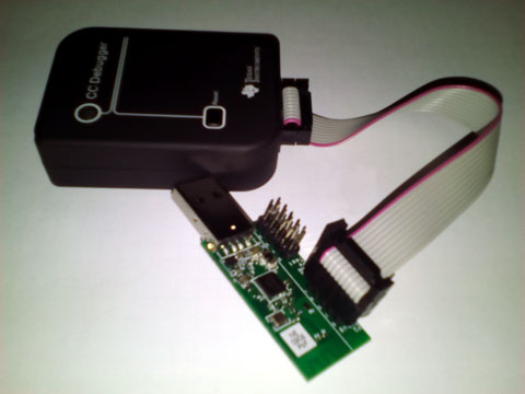
Now it’s time to program the CC2511 SoC with the sniffer firmware. Insert your CC2511-dongle into USB-port of your PC and connect it to the CC-Debugger. If you see green led on the CC-debugger then everything is fine. Otherwise reconnect the CC-Debugger.
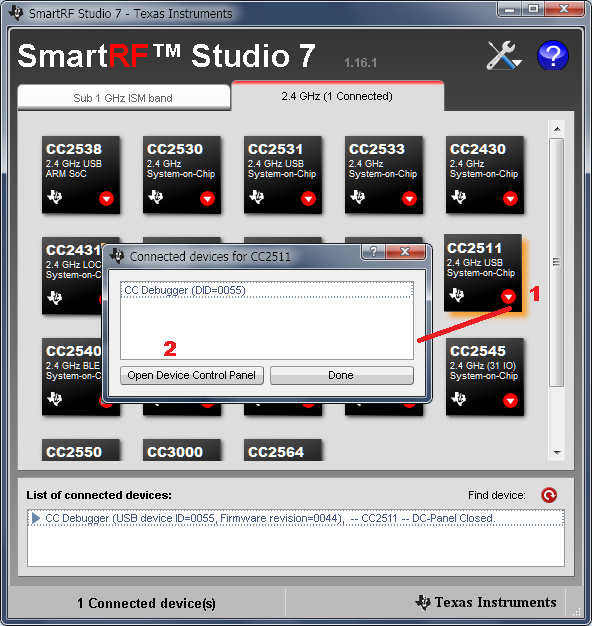
Start the “SmartRF Studio 7” and you will see its main window.
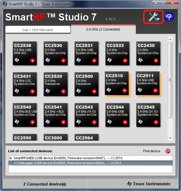
1) Select 2.4 GHz tab with CC24xx and CC25xx devices.
2) In the list of connected devices highlight the CC Debugger.
3) Click at “Tools” button in the top right corner of the window.
You will see the SmartRF Flash Programmer dialog window.
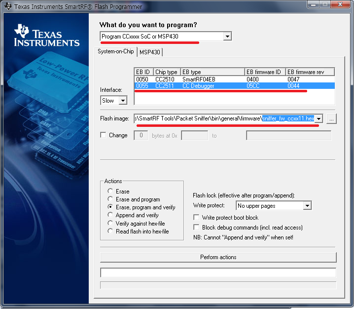
1) In the drop-down list select “CCxxxx SoC” option.
2) In the list of connected devices select CC2511 (CC Debugger)
3) Locate the sniffer firmware hex-file “sniffer_fw_ccxx11.hex”.
Check everything once again and press “Perform actions”.
Before we start SmartRF Packet Sniffer, I think it is a good idea to view configuration register values.
3. Configuring RF-registers
There are a lot of wireless devices and a great number of communication protocols. At design time we must select communication rules identical for every device in our network. It is possible to select “base frequency”, “modulation format”, “data rate”, “channel spacing” and many others. These parameters are configured by setting values to more than a dozen MCU registers. If you wish to let your devices communicate with each other you must configure these registers properly, usually identically to the same devices.
It is supposed that CC2511 and CC2510 devices can work together. The RF-parts, SPI/UART and many other components of these SoCs are identical. The CC2511 has USB-port and operates at 24MHz. The CC2510 operates at 26MHz. That is why the configuration register values of these SoCs are different.
SmartRF Studio is used to configure and test RF-devices from Texas Instruments. The application helps developers evaluate the wireless communication at an early stage in the design process.
1) Click the arrow on CC2511 icon and select “Open RF device in off-line mode” menu item.
2) Open device control panel. It is possible to work in off-line mode.
The “CC2511 – Device Control Panel” will appear on your screen. In this window you will see many parameters that are used for RF-device configuration. There is a set of recommended/typical register settings for all devices. Anyone can get basic register values, read and write individual RF registers.
The top list contains most popular RF-protocols and helps us quickly fill communication parameters in medium part of the window. The RF parameters can be set manually. You should change these values very carefully, because they affect one or more MCU registers listed in the right pane of the window.
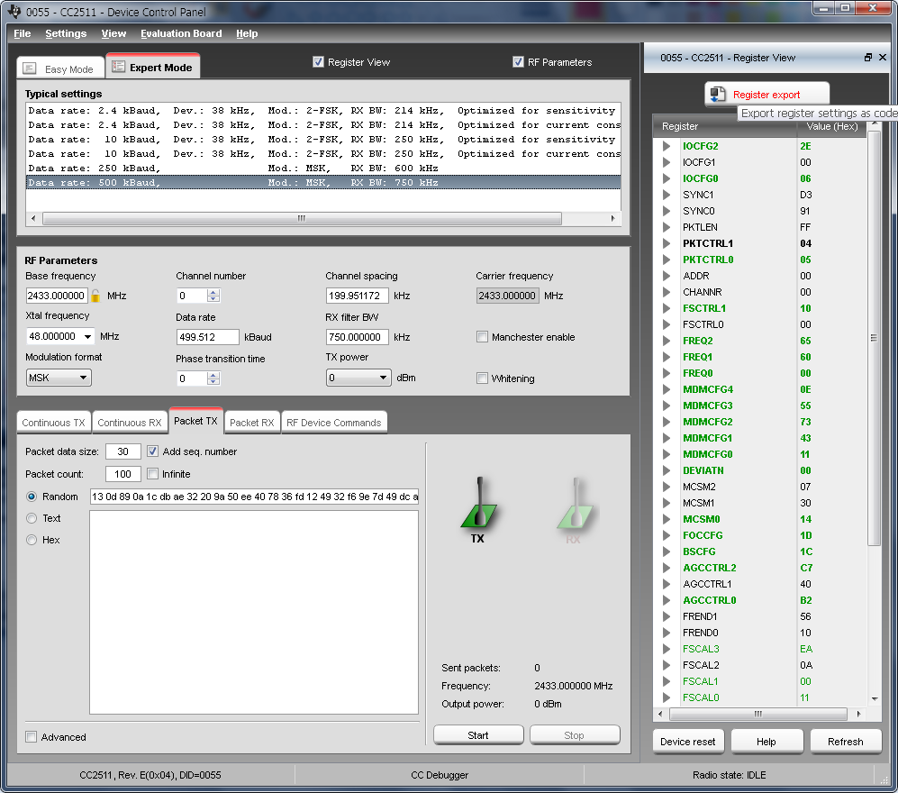
At the bottom of the window there are buttons and input fields for testing RX and TX features. This area is active only when a RF-device is connected. It can be used at design time to test the link between devices and find proper values for RF registers. You can send and receive packets between nodes. It is possible to set the radio in continuous TX and RX states.
Another great feature of this application is a “Register Export” tool. The configuration registers and its values can be exported to your IDE (IAR Workbench) in different formats.
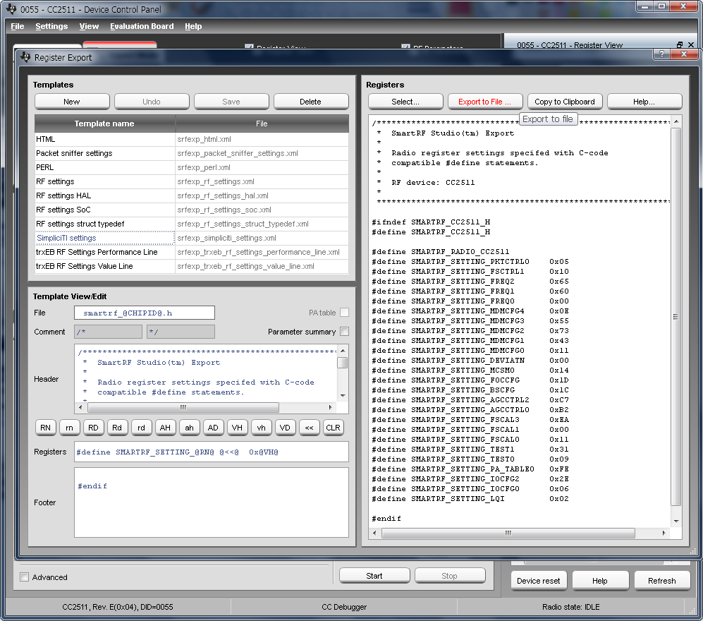
I think most useful export features are:
1) header file with definitions in C language
#define SMARTRF_SETTING_FREQ2       0x65
#define SMARTRF_SETTING_FREQ1       0x60
#define SMARTRF_SETTING_FREQ0       0x00
2) code fragment with HAL function calls
halRfWriteReg(PKTCTRL0,0x05); //Packet Automation Control
halRfWriteReg(FSCTRL1,0x0A);  //Frequency Synthesizer Control
3) C-code with direct assignments to RF-registers
FREQ2     = 0x65; // frequency control word, high byte
FREQ1     = 0x60; // frequency control word, middle byte
FREQ0     = 0x00; // frequency control word, low byte
So, it is very easy to export radio configuration code. It is especially useful for generation of configuration register values, for practical testing of the RF system and for finding optimized external component values.
4. RF protocol sniffing
The SmartRF Packet Sniffer is a PC software application that can display and store radio packets captured by a listening RF device. It lets you look deeper to see and verify what is going on with your RF communication. It is similar to a logic analyzer, but it doesn’t analyze SPI or I2C protocol. It is used for testing and debugging wireless protocols. The Packet Sniffer can filter and decode packets and display them in a convenient way.
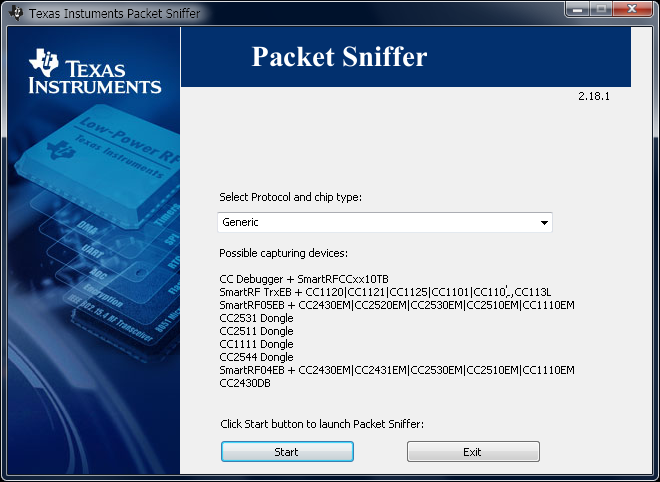
You can find “Packet Sniffer” icon at your desktop and launch the application. The dialog window will ask you for desired protocol and device family. The CC2511 doesn’t support ZigBee, neither Bluetooth LE protocols. So, we will select “Generic” (raw packet data) option. Sometimes “SimpliciTI” protocol can be useful, because it is supported by great number of TI devices.
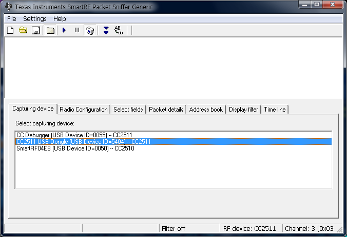
After you press “Start” button you will see an empty main application window with seven tabs in the bottom of the window. The first tab lists all compatible RF-devices. Here we select the CC2511 dongle which is already programmed with the sniffer firmware.
The second tab is called “Radio Configuration”. It is used for setting MCU registers values. It is possible to load device configuration data and register values from PRS-file (click “Browse…” button). Configuration files for most popular TI protocols are located in this folder: “C:\Program Files\Texas Instruments\SmartRF Tools\Packet Sniffer\bin\general\config\cc2511\”.
When radio registers are successfully configured they can be saved into a file (use “Write to file” button). PRS-file is a text file that can be modified with any editor, for example “Notepad”. This file contains three fields: register name, register address, register value. All fields are separated with a “|” sign. There could be optional fourth field with a comment. I have prepared two configuration files for cc2511 and cc2510 devices.
PKTCTRL1 |0xDF03|0x04
PKTCTRL0 |0xDF04|0x45
FSCTRL1  |0xDF07|0x10
FSCRTL0  |0xDF08|0x00|Some comment
To start packet sniffing you should press “>>” start button in the toolbar. In my example, I have a “flooder/counter” firmware in SmartRF04EB kit. This firmware continuously transmits radio-packets as a sequence of numbers “00 01 02 03” etc.
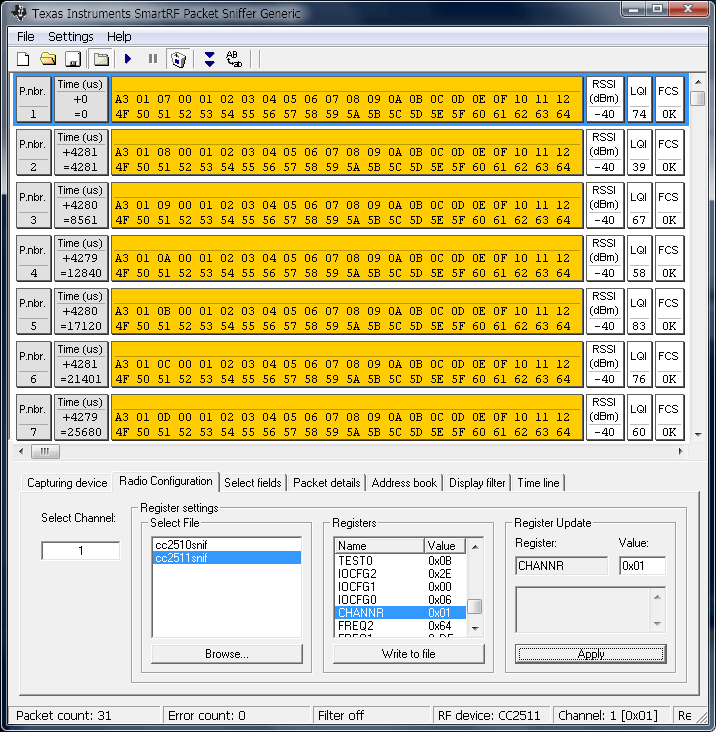
If you see many yellow packets then your software seems to be working. The empty window means something is wrong. Possible reason is incorrect values in configuration registers or wrong channel number or slow signal. You should check every register value in the list and “Apply” correct values.
Every line in the SmartRF Packet Sniffer window corresponds to a packet. There are six fields:
1) packet number,
2) time stamp,
3) packet data (payload),
4) RSSI – received signal strength indication,
5) LQI – link quality indicator,
6) FCS – frame check sequence.
When the sniffer is working there are a lot of data blinking on the screen. It is a good idea to “Pause” the sniffer or apply a filter. The third tab lets developer select fields to be displayed or hidden. Of course all captured data can be saved into file.
Hope this post will be useful to you. I would be happy to test any new wireless devices from hardware vendors. Feel free to contact me.
P.S. Nordic Semiconductor has similar sniffer software and devices. I wish they were more friendly and open to developers.